

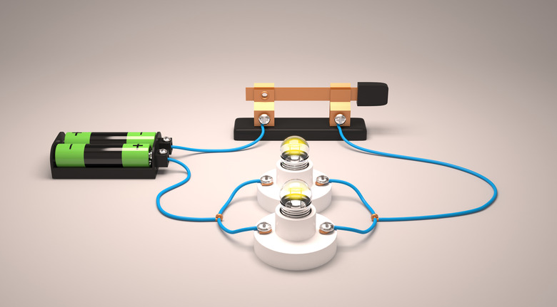
Deciding between a parallel or series circuit comes down to one question: should every component share a single path for electricity, or should each one get its own branch? That choice changes how much voltage each part receives, how much current the power source has to deliver, and what happens when one part fails. A series layout is simple and uses less wire, but a single break shuts everything down. A parallel layout keeps devices running independently at full voltage, which is why your home relies on it. This guide walks through both designs, the math behind them, and the everyday places where you already meet each one.
Table of Contents
What is a series circuit?
A series circuit connects every component end to end, so electricity has exactly one route from the positive terminal of the source, through each part in turn, and back to the negative terminal. There are no branches or junctions. Because there is only one path, the same current flows through every component, whether it is a resistor, a bulb, or a switch. Understanding this single-loop layout is the first half of any parallel or series circuit comparison.
The source voltage, however, gets divided along the way. Each component takes a share, called a voltage drop, and the drops add up to the total supplied voltage. Resistances also stack: the total resistance equals R1 + R2 + R3 and so on, which means it is always larger than the biggest single resistor in the chain. Add another bulb and the whole circuit becomes more resistive, so less current flows and every bulb dims.
The biggest drawback is fragility. If any component burns out or a wire comes loose, the only path is broken and the entire circuit stops working. Simple flashlights, which stack batteries end to end, and older strings of holiday lights are classic examples of series wiring.
What is a parallel circuit?
A parallel circuit splits the current into two or more branches, and each component sits on its own branch between the same two connection points. As Britannica’s overview of parallel circuits explains, the voltage across each branch is the same, while the current in each branch can differ depending on its resistance.
The branch currents add up to the total current leaving the source. Resistance behaves in the opposite way to a series chain: you add the reciprocals, so 1/R total = 1/R1 + 1/R2 + 1/R3. The result is always smaller than the smallest individual branch resistance. This reciprocal rule is the main mathematical split in any parallel or series circuit problem. Every branch you add gives the current another path, lowers total resistance, and makes the source work harder.
The big advantage is independence. If one branch opens because a bulb fails or an appliance is unplugged, the other branches keep their full voltage and carry on. That reliability is the reason wall outlets, household lighting circuits, and car headlights are wired in parallel.
Telling a parallel or series circuit apart
The quickest way to identify a parallel or series circuit is to trace the path with your finger. If you can follow one unbroken loop that passes through every component, you are looking at a series layout. If the wire forks at a junction and rejoins later, with components sitting on separate forks, the design is parallel. The table below summarizes how the two layouts differ on the properties that matter most.
| Feature | Series circuit | Parallel circuit |
| Current paths | One single path | Two or more branches |
| Current | Same through every component | Splits among branches; branch currents add up |
| Voltage | Divided among components | Same across every branch |
| Total resistance | Sum of all resistances (R = R1 + R2 + …) | Lower than the smallest branch (1/R = 1/R1 + 1/R2 + …) |
| Adding a component | Raises resistance, lowers current | Lowers resistance, raises total current |
| One component fails | Whole circuit stops | Other branches keep working |
| Identical bulbs | Dimmer as more bulbs are added | Each bulb stays at full brightness |
| Wiring needed | Less wire, simpler layout | More wire and connections |
| Batteries | Voltages add, amp-hours stay the same | Amp-hours add, voltage stays the same |
| Typical uses | Flashlights, switches, fuses, mini light strings | Home outlets, lighting circuits, car headlights |
Even the difference between a parallel or series circuit is not always clean in real devices. Most practical electronics mix both, with a switch or fuse in series feeding several branches wired in parallel. Engineers call this a series-parallel or combination circuit.
The math behind a parallel or series circuit
Numbers make the contrast easy to see. Take three identical 100-ohm resistors and a 12-volt battery, and wire them as a parallel or series circuit in turn. In series, total resistance is 300 ohms. Ohm’s law (current equals voltage divided by resistance) gives 12 / 300 = 0.04 amps, and each resistor drops 4 volts, which together add back up to 12.
Rewire the same three resistors in parallel and the picture flips. Total resistance falls to about 33.3 ohms. Each branch sees the full 12 volts and draws 0.12 amps, so the battery supplies 0.36 amps in total, nine times the current of the series version. So which parallel or series circuit arrangement uses more energy? The parallel one, delivering about 4.3 watts against roughly 0.5 watts in series, which means it drains the battery much faster.
The same logic explains bulb brightness. Put two identical bulbs in series and each gets roughly half the voltage and half the current it would receive alone, so each glows at around a quarter of its normal power. Put them in parallel and each runs at full brightness, while the source supplies double the current. Real filaments change resistance as they heat up, so the exact figures shift slightly, but the pattern holds.
Where each layout shows up in everyday life
You meet a parallel or series circuit every time you plug something in, flip a switch, or load batteries into a gadget. Your home is the clearest example. Receptacles on a branch circuit are wired in parallel, so each one gets the same nominal 120 volts in North America whether one lamp or five devices are plugged in. The breaker or fuse protecting that circuit sits in series with it, so when too much current flows it trips and cuts power to every outlet it feeds. Wall switches are also in series with the lights they control. Mains voltage is dangerous, so leave any changes to household wiring to a licensed electrician.
Traditional incandescent mini lights show the series layout and its weakness. Early strings went completely dark when one bulb failed. Modern incandescent mini bulbs include a tiny shunt that becomes conductive when the filament breaks, letting current bypass the dead bulb so the rest of the string stays lit. Each surviving bulb then receives slightly more voltage, which is why burned-out bulbs should be replaced promptly.
Battery packs use both layouts on purpose. Two 6-volt, 4.5 amp-hour batteries in series make a 12-volt, 4.5 amp-hour pack. Four 12-volt, 100 amp-hour batteries in parallel make a 12-volt, 400 amp-hour bank that runs longer at the same voltage. Choosing a parallel or series circuit for a battery bank depends on whether your equipment needs more voltage or more runtime, since the total stored energy in watt-hours is the same either way.
Measuring tools follow the same rules. An ammeter goes in series because the full current must pass through it, and its very low internal resistance barely affects the circuit. A voltmeter goes in parallel across a component because its very high resistance means it draws almost no current.
Choosing a parallel or series circuit for your project
When people ask whether a parallel or series circuit is better, they usually mean which one suits a specific job. There is no universal winner, but a handful of questions settle most decisions quickly:
- Must every device keep working if one fails? Choose parallel.
- Does each device need the full source voltage? Choose parallel.
- Do you need higher voltage from low-voltage cells? Choose series.
- Should one switch or fuse control everything? Place it in series.
- Is the build simple, with tight space or budget? Series needs less wire.
The parallel or series circuit question gets more specific with LEDs. In a series string, all LEDs share one current and their forward voltages add up, so the supply must exceed that combined total with some headroom left for the current-limiting resistor. In parallel, each LED should get its own resistor, because LEDs do not share current evenly and one can hog the supply, overheat, and fail early. Checking datasheet values before soldering saves burned parts and wasted time.
Frequently asked questions
Are household outlets a parallel or series circuit?
Household outlets are wired in parallel. That keeps each receptacle at the same voltage and lets appliances run independently. Protective and control devices such as breakers, fuses, and switches are placed in series with the loads they serve.
Which drains a battery faster, a parallel or series circuit?
With the same components and the same source, the parallel layout drains a battery faster. Its lower total resistance draws more current. Three identical resistors in parallel pull nine times the current of the same three resistors in series.
Can a circuit be both series and parallel?
Yes. Combination circuits mix both layouts, and most real devices use them. To analyze one, reduce each parallel group to a single equivalent resistance, then add that value to the resistances wired in series with it.
Picking the right path for the current
The choice between a parallel or series circuit is really a choice about paths. One path means shared current, divided voltage, less wiring, and an all-or-nothing failure mode. Several paths mean shared voltage, added current, and devices that keep working on their own. Match the layout to what your devices actually need, keep fuses and switches in series with the loads they protect, and you will rarely go wrong.

